
Medium-voltage distribution systems require equipment that can provide reliable switching, isolation, and protection while making efficient use of installation space. The SRM6-12 ring main unit is a compact solution designed for secondary power distribution, where it can connect distribution cables, protect transformers, and support both ring and radial network arrangements.
This article explains what an SRM6-12 ring main unit is, how it works in a distribution network, its common applications and configurations, and the key technical information buyers should consider before selecting equipment or requesting a quotation. RMU
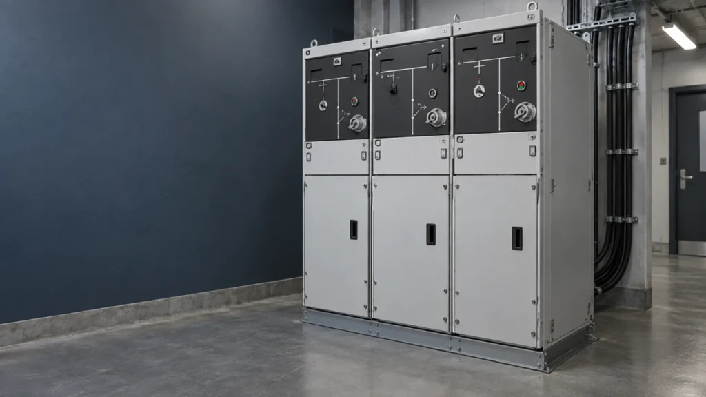
What Is a Ring Main Unit?
A ring main unit is a compact medium-voltage switchgear assembly used in secondary power distribution. It combines functional units for switching, isolation, and protection, depending on its configuration.
A typical arrangement includes cable switching units and a transformer protection unit. These allow the equipment to connect distribution cables and supply a transformer within one coordinated assembly.
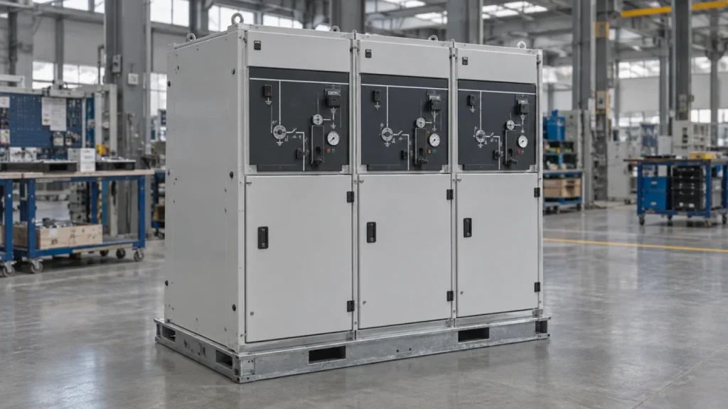
The SRM6-12 operates on the medium-voltage side of the system. The transformer changes the voltage, while the downstream low-voltage switchgear distributes power to individual loads.
Although its name refers to a ring network, an SRM6-12 can also be used in a radial distribution arrangement when its configuration suits the system.
How Does an SRM6-12 Work in a Distribution Network?
In a ring network, distribution cables connect several substations along a loop. Many such networks operate with one point normally open.
This arrangement can provide an alternative supply path. If a cable section develops a fault, protection equipment clears the fault, and the affected section can then be isolated. Supply to healthy sections may be restored through another path, subject to the network design, available capacity, and operating procedures.
An SRM6-12 provides the switching functions needed within this arrangement. However, installing an SRM6-12 alone does not guarantee automatic supply restoration. Automation requires suitable protection, controls, communications, and switching logic.
In a radial network, power reaches the load through a single supply path. An SRM6-12 can still provide compact switching and transformer protection, but it does not create an alternative supply route by itself.
Where Are SRM6-12s Used?
SRM6-12s are commonly considered for installations that need compact medium-voltage distribution equipment, including:
- Industrial facilities:Distributing power to transformers serving production areas and other site loads.
- Commercial developments:Supplying transformers for offices, shopping centres, and mixed-use buildings.
- Residential distribution networks:Connecting local transformer substations.
- Prefabricated substations:Providing the medium-voltage switching and protection section of an integrated installation.
- Infrastructure and renewable energy projects:Supporting distribution or collection arrangements where the equipment ratings and functions meet project requirements.
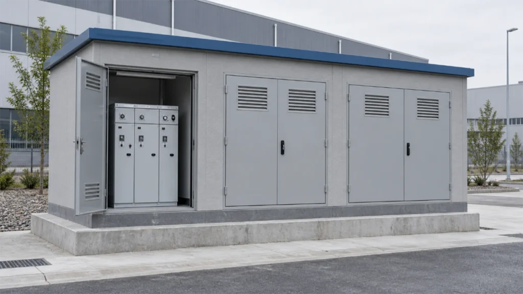
The suitability of an SRM6-12 depends on the electrical system and operating requirements. Compact dimensions alone are not enough to establish that it is the right choice.
Understanding Common SRM6-12 Configurations
SRM6-12 configurations are best understood by the function of each unit, rather than by the number of compartments alone.
| Functional unit | Main purpose | What buyers should confirm |
| Cable switching unit | Connects or isolates a distribution cable, typically using a switch-disconnector | Required switching duties, current rating, and earthing arrangements |
| Switch-fuse transformer protection unit | Combines switching with fuse-based transformer protection | Suitable fuse selection and coordination with the transformer and downstream protection |
| Circuit-breaker protection unit | Provides fault interruption with a suitable protection and sensing system | Protection functions, relay settings, sensing devices, and auxiliary supply requirements |
| Metering unit | Accommodates measurement equipment where required | Utility requirements and the specified metering arrangement |
A load-break switch and a circuit breaker perform different duties. A load-break switch is intended to switch specified load currents; it should not be assumed to provide the same fault-interruption capability as a circuit breaker.
Two Cable Units and One Transformer Protection Unit
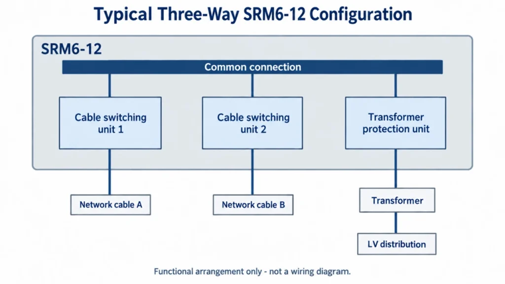
A common arrangement includes two cable switching units and one transformer protection unit.
The two cable units connect the SRM6-12 to the distribution loop. The protection unit supplies the local transformer. This arrangement is often suitable for a substation serving one transformer, but its ratings and protection scheme must still be checked against the project.
Multiple Transformer Feeders
A site with several transformers may require additional protection units. Each transformer feeder needs protection appropriate to its transformer and connected system.
Configurations for Future Expansion
Some SRM6-12 designs are extendable, while others have a fixed arrangement. If additional feeders may be needed later, the extension capability should be specified at the enquiry stage.
Manufacturer configuration codes vary. Buyers should confirm the actual functions on the single-line diagram rather than assume that similar model codes describe identical equipment.
Switch-Fuse or Circuit-Breaker Protection?
Both arrangements can be used for transformer protection, but the choice requires a coordination study and consideration of operating needs.
A switch-fuse arrangement can provide a compact solution. Fuse selection must account for transformer characteristics, including inrush current, and coordination with other protective devices. The suitability of the complete switch-fuse combination also matters.
A circuit-breaker arrangement can support adjustable protection functions through a suitable relay and sensing system. It may be appropriate when a project needs more detailed protection settings, monitoring, or integration with remote controls.
Neither option should be selected solely by price or transformer capacity. The decision should consider fault levels, protection coordination, utility requirements, maintenance practices, and future operating needs.
What Should Buyers Check Before Selecting an SRM6-12?
1. System Voltage and Insulation Requirements
Specify the system nominal voltage, highest voltage for equipment, frequency, and required insulation levels.
Insulation performance must also suit the installation environment. Altitude, pollution, and other site conditions may affect equipment selection.
2. Rated Current
Confirm the required current rating for each circuit and the relevant common current path.
Cable units and transformer protection units may have different ratings. The required values should follow the expected load and planned expansion.
3. Short-Circuit Ratings
Provide the prospective short-circuit current and required fault duration at the installation point.
Short-time withstand current, peak withstand current, making capacity, and breaking capacity describe different duties. Applicable ratings must be checked for the assembly and its individual functional units.
4. Protection and Network Operation
Define whether the system is radial or ring-connected, how it normally operates, and which protective devices must coordinate.
Also identify any requirements for remote switching, fault indication, monitoring, or automatic restoration. These functions need to be specified explicitly.
5. Installation Environment and Access
Confirm indoor or outdoor installation, ambient temperature, altitude, humidity, and exposure to dust, salt, or condensation.
Check cable entry, cable bending space, operating access, maintenance access, and any pressure-relief requirements. An SRM6-12’s enclosure dimensions do not represent the full installation space it needs.
Where internal arc classification is required, specify the relevant accessibility conditions, current, and duration. The room arrangement must follow the manufacturer’s installation requirements.
6. Insulation Medium and Service Requirements
SRM6-12s are available with different insulation technologies. Buyers should consider local requirements, maintenance arrangements, environmental policies, and end-of-life handling when assessing the available designs.
Do not assume that all SRM6-12s use the same insulation medium or require the same servicing procedures.
What Information Is Needed for an SRM6-12 Quotation?
A clear enquiry helps suppliers propose a suitable configuration and reduces clarification during the quotation process.
Prepare the following information where available:
- Project location and applicable utility specifications.
- System voltage and frequency.
- Single-line diagram and required feeder functions.
- Transformer quantity, ratings, and relevant technical data.
- Circuit current ratings and prospective short-circuit current.
- Protection, metering, monitoring, and remote-control requirements.
- Indoor or outdoor installation and environmental conditions.
- Cable details, entry direction, and available installation space.
- Required future extension capability.
- Applicable standards and required test documentation.
If some details are still being developed, identify them as pending. A preliminary quotation should clearly state the assumptions used.
Common Purchasing Mistakes
Several avoidable mistakes can result in an unsuitable selection:
- Ordering by the number of “ways” without defining each unit’s function.
- Treating all current ratings as interchangeable.
- Assuming an SRM6-12automatically restores power after a fault.
- Selecting transformer protection without checking coordination.
- Reserving only the equipment footprint and overlooking operating or cable space.
- Assuming every compact SRM6-12can be extended later.
A single-line diagram, equipment schedule, and installation layout provide a stronger basis for selection than a product photograph alone.
Discuss Your SRM6-12 Requirements with CMC Electric
The right SRM6-12 configuration depends on your distribution network, transformer protection requirements, and installation conditions.
Planning a new installation or upgrading an existing system? Share your single-line diagram, system voltage, transformer details, and site requirements with CMC Electric to discuss product selection and quotation requirements.